Vehicle Creation Workflow
| Language: | [[::Vehicle Creation Workflow|English]] |
|---|
Contents
| Language: | [[::Vehicle Creation Workflow|English]] |
|---|
Introduction
"There are a million ways to model a car. Games like Forza or Gran Turismo go the high poly route, using 100 or even 200 thousand polies to make photo-realistic bodyshells (usually laser-scanned). The interiors go the same way. The downside to this method is that unless the lighting in the engine is absolutely amazing, it’s going to look quite fake without proper textures (with AO and grime and all that). In addition, the cars in these games lack the detailed frame, suspension, and underbody components that the cars I’m making for BeamNG have."
"The opposite end of the spectrum would be the vehicles in a game like Mafia 2. These are clearly made by baking normal maps from a high poly model onto one with much less geometry. This is a nice workflow and quite standard for most game assets, but it’s a bit too labor-intensive and limiting for the way I like to do things. It’s also restrictive if you want to make variants, as the low poly geometry cannot be changed at all without ruining the shading that the normal map provides. If you look at the suspension and underbody on cars in Mafia 2 they appear to use common textures, not even with normal maps, and it’s all quite inaccurately modeled and fudged."
Car body
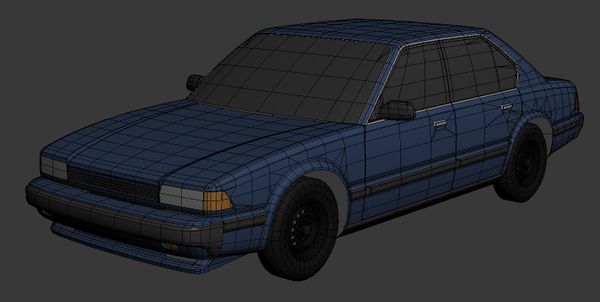
"So the way I do vehicles is not something I’ve seen done in games before. I model the car sort of mid-poly, body shell first. The very first thing I do is place wheels/tires at the correct wheelbase, track width, and diameter according to a real car. I get the car’s shape roughed out, and begin to smooth it to its final density, trying to maintain a nice grid-like topology across the whole thing for good deformation. Any hard edges, shoulder lines, stuff like that that are part of the main shell I smooth with “control edgeloops,” that is, edgeloops on either side of the hard edge which don’t change the shape or silhouette at all but simply control the smoothing, softening the edge. In general, the whole body shell is just one smoothing group (except for where there are panel cut lines and whatnot)."
"Once the shell is complete I detach each panel, spacing them apart what seems like a realistic amount (a few millimeters)."
"Then I model the undersides of the panels, door jambs, and all that kind of stuff consulting real world photos and references very closely. You can find great refs by googling something like <carname> scrapped, stripped, wrecked, build, etc. You’ll find lots of cars with the panels taken off or the frame by itself."
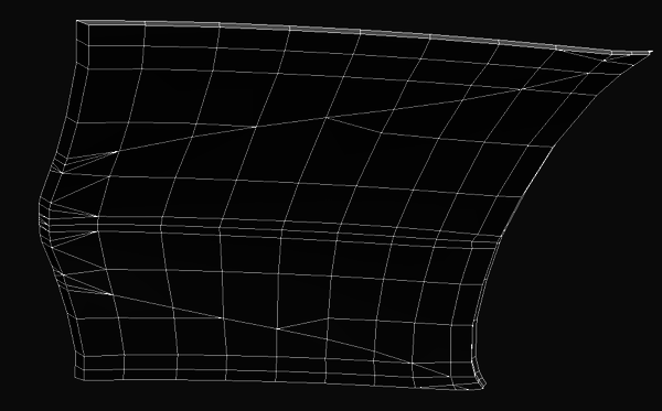
"Every body panel will have some complex-looking underside detail – usually some structural panel bolted to the underside with some cross members and cutouts and indents and all kinds of fancy stuff. Conventional AAA game art would have you model all of that in a high poly mesh, which would take ages. I leave all of that for later (I’ll explain how I do it shortly). The underside of a hood or trunk, for example, is pretty much just “flat”, retaining the same basic grid as the outside for good deformation but removing any sharp character lines and simplifying the geometry as much as possible. I give it a bit of volume to represent the depth of the structural panel as well."
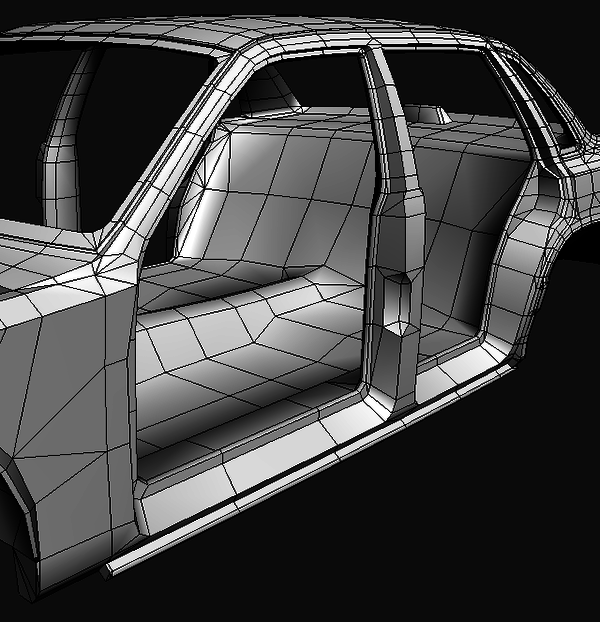
"Door jambs are a bit tricky, but you can usually figure them out from looking at a photo (there are plenty of photos). The door itself would just be the inverse of the door jamb. There’s usually some indents and cutouts and hinges and other details, which I’ll talk about later. I don’t model any of that at this stage, except the rubber seal(s) running the perimeter of the door opening. When you UV long, thin things like rubber seals, straighten them out completely. That way you don’t get any aliasing on the nice normal mapped beveled panel gaps."
"I also model the frame (if it’s body-on-frame) according to reference photos with fairly low poly density, as well as all the suspension components and running gear. It’s important to keep polygon counts down here as these parts aren’t seen much and to me they look better if they’re lower res because the flaws are a lot less noticeable that way."
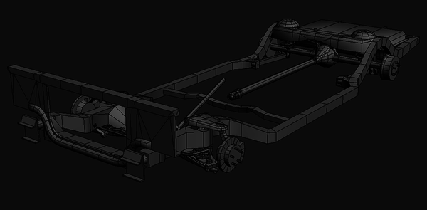
"It can seem really daunting at first, looking at a photo of the underside of the car with all the (seemingly) millions of little parts. But if you study it for a while, you can break it down (and there aren’t that many components). There are usually mounting points for the suspension arms, some kind of subframe perhaps, the arms themselves (tubular or stamped steel, it depends), the wheel spindle that attaches to the arms, the half-shaft, tie rod, etc. One of the most valuable skills you can have in this situation is to be able to look at a photo of a real car’s suspension and identify all the individual components, what they do, and how to best model them. It’s not something that can easily be taught – for me it’s been a lot of trial and error. I didn’t model anything properly on my Rigs of Rods cars because back then it was still totally confounding for me."
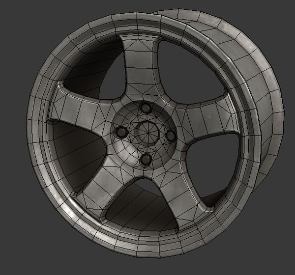
"An important topic is how many sides to put on a cylinder. It’s all about size and visibility. A tiny pin running through a U-joint? Give it 4 sides and it’ll look fine. A small pin running through the hinge point of an A-arm? 6 sides will do. Same for things like tie rods and half-shafts. 8 is plenty for something like a driveshaft or the circular end of a suspension link. I see so many people go overboard with cylinders. Cylinders are huge poly hogs and models can look really unprofessional if the polygon density is inconsistent. You don’t want to have 24 sides on a tiny little cylinder next to something else that’s really blocky. Tires and wheels are another area where segment count is critical. I’m using 32 sides on my tires because it’s divisible by a lot of numbers and it seems to be a good compromise between polygon count and smoothness. Wheels themselves depend on spoke count and bolt pattern. You’ll usually want to find a number that’s a common multiple of the spoke count and bolt pattern. For example, a 5 spoke wheel with 4 bolts could work with 30 segments. Here’s the wireframe of one:
"Which brings me to another point. When should you bake normals from a high poly and when should you paint them in Photoshop?
Well, it’s really up to you. I find it’s best to bake normals for simple things like wheels because they go on their own texture map, they’re geometrically simple, and it’s quite easy to get a nice smoothness and save a lot of polies (like I said, cylinders are poly hogs). The high-poly model is easy to make and the low-poly is easily adapted from the high-poly.
In the case of a whole car, I almost never bake normal maps (except interiors – I’ll cover that in part 2 below). To get the nice, smooth beveled panel gaps you see on my cars, I have a special method."
"First, UV the whole car with this in mind: UV seams correspond to hard edges. When you have the whole car modeled, there are going to be a lot of parts. It can be daunting to try to UV all of them. I’ll open up my 3D modeling program and unwrap a few parts at a time and keep whittling away at it. Eventually, everything is unwrapped and you can merge them together to pack the UVs. Make sure you put the lights (and anything else that needs to glow/break like glass or gauges) on a separate map. Everywhere you want a smooth bevel to soften out a hard edge, put a UV seam. Another important point about UV mapping: texel density. In addition to making sure that there’s no stretching on your body panels (make sure curved surfaces are “flattened” in the UVs so every polygon gets the right density), it’s important to scale the underbody/frame/suspension/running gear stuff way down. The bodywork is what’s visible the most, so it should get the highest res, and it echoes my point earlier about things looking better lower-res if you have to fudge details. I usually scale everything that’s not the main body shell down to about 50-60% of its regular resolution (compared to the body)."
"As far as symmetry goes, it’s up to you. I like to use symmetry seams wherever possible to save on UV space. Most of my cars have a mirror seam along the middle of the roof, but the hood, bumpers, and trunk get both halves mapped separately. This means you can’t put lettering and such on the doors/body sides without it getting mirrored across the other side, but it also saves hugely on UV space. You can always use decals (floating geometry with alpha transparency) to do lettering, like on the police Grand Marshal."
"A point about texel density again: Map size is critical. It depends on the size of the vehicle and how many parts it has. I tend to use 2048×1024 for most cars (Grand Marshal, Bolide, Moonhawk). The Covet is using a 1024×1024 because it’s small and simple, and the D15 uses a 2048×2048 because it’s big and has more parts. I almost always texture at double resolution because it looks much better and more details are preserved."
"The next step, once your UVs are packed, is to bake out a white diffuse map with 0 padding (it basically outputs every UV island in white against a black background). Bake it at double resolution so it’s not aliased. Bring this into your image editor and use it as a mask for a solid white layer. Make 3 versions of this layer: one as-is, one with the selection expanded by 1 px, and one with the selection contracted by 1 px. Collapse each layer onto its own black background and run each through a height-to-normal-map filter. Then, overlay the 3 layers onto each other. You now have nice bevels everywhere there’s a UV seam. There’ll be maybe 20-30 minutes of removing it where it’s not needed, like on the ends of cylinders where they wrap around and on symmetry seams, but it’s so much easier than making a high poly with beveled panel gaps and it gives almost the same result with very little work. This is the workflow I’ve been using on every vehicle after the first 3 (hadn’t figured this out yet when I was doing the D15, Grand Marshal, and Covet)."
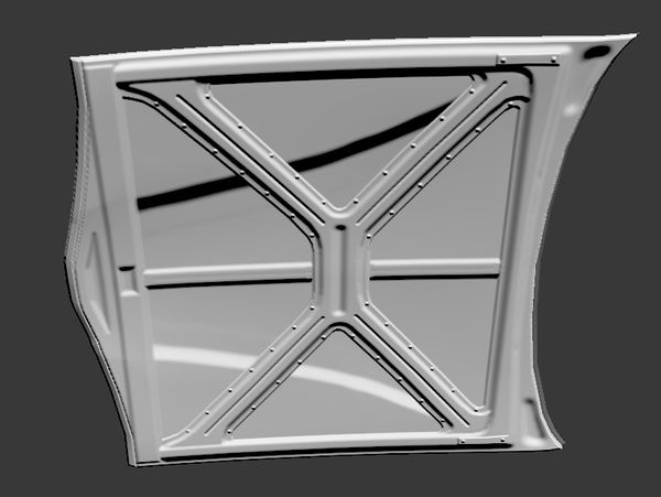
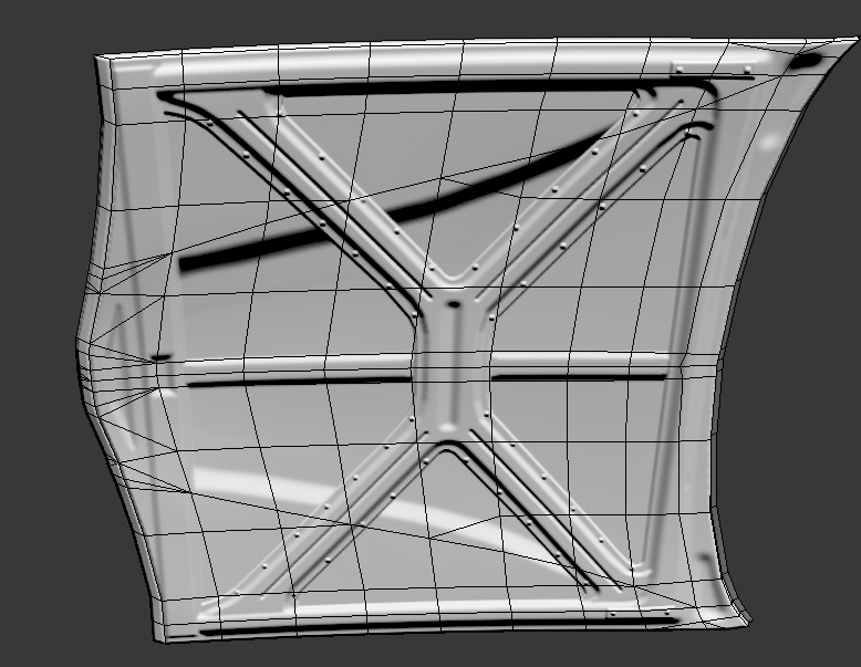
"After the first 'bevel' pass, it’s time to start 'modelling' in Photoshop (or your preferred image editor). You can just start drawing in things like indents, bolts, and whatever, thinking in terms of a heightmap. So a cutout would be a sharp black shape on a white background, while a smooth indent would be softer. A bolt would simply be a small sharp white circle. Run all of these things through the normal map filter and overlay them on themselves if needed to increase their intensity. It took only 30 minutes for me to “model” all of this underside detail on the hood of the Moonhawk:
"Continue along, consulting reference images to paint all these details into the normal map everywhere they’re needed. You can do this with engines too: start with a really simple mesh, and add all the details with the normal map in your image editor. I did that with all of my car engines. They’re not exactly high res or detailed, but I think they’re at least visually pleasing and decently convincing. Engines are one of those things where I still can’t wrap my head around all the details so I tend to fudge things. One of these days I’ll be able to model an engine with some nice detail. 🙂 There’s also a whole bunch of crap in the engine bay, like tanks, pumps, and other gizmos that I just fudge the hell out of. You might notice a lot of my cars have a mesh called 'engbaycrap'." 😀
"Once the normal map is complete, it’s time to bake ambient occlusion. Space apart every detachable/removable part a good way away so you don’t get any strange black shadows when a part falls off. Make sure the normal map is applied in the renderer. You may want to boost the intensity to 2x or 3x so the details really cast nice ambient shadows. In 3DS Max, the way to bake AO is simply by making a skylight and setting it to cast shadows. Set the ray bias to as low as possible. Make sure supersampling is disabled in the renderer (it takes forever to render if it’s enabled). Boost the skylight brightness so the shadows aren’t too broad. They should be tightly confined to crevices."
"When the bake is done, shove it into your diffuse and specular maps with multiply mode. Run levels on it to get the whites really white and eliminate any broad shadows that are flooding across flat surfaces. I like to use the inverse of the AO as a mask for a brown grime layer. Keep it subtle. It gives a bit of nice realistic character to the surface without overdoing it. There will hopefully be a dynamic dirt system in the future (using vertex blending) so the real dirtiness can be done dynamically."
"Another important step is differentiating the materials. You’ll have parts that are car paint, parts that are dark metal (frame, suspension, etc.), parts that are chrome, interior carpeting, and whatever else. In my case I assign all of these materials beforehand to the proper polygons, give each material an extreme colour (like 255, 0, 0 for pure red), and bake a diffuseMap (with a good amount of padding). You can use the red, green, and blue channels of this map as masks for each type of material (car paint, chrome, black). It saves a lot of time manually selecting which part of the car is which in your UV maps."
"There’s a very convoluted way that reflectivity works in Torque3D. You basically “cover up” a base of chrome with non-reflective texture. So the alpha channel of a diffuse map is like an inverted reflectivity map. Black is chrome and white is pure colour. I usually just take my specular map, tweak the levels, and invert it to make my reflectivity map. I tweak the levels so things that have low specularity end up with no reflectivity (like black rubber), but chrome and car paint are still shiny."
"If you want to set your vehicle up so that it can be recolored without editing any textures, you’ll need a separate colour map (called vehiclename_c on my vehicles) which is solid white with a finely tuned alpha channel. Everything is black except the areas which receive body paint, which are a shade of gray (tuned for the right balance of shine and colour strength) mixed in with the AO. On the main diffuse map, all the areas that receive body color should be pure black (except whatever grime might sit on top) and quite dark/black in the diffuse alpha channel. In this way, removing the colour map would effectively give the car a chrome finish. I recommend using one of my vehicles’ materials as a template for yours."
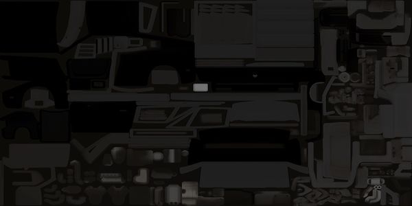
The diffuse map of the Civetta Bolide (half size):
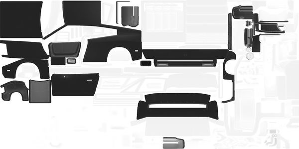
The diffuse alpha:
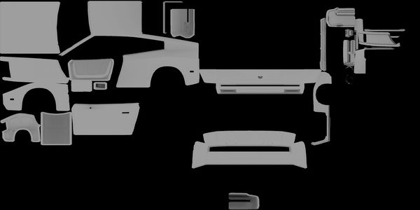
The color map alpha:
Car interior
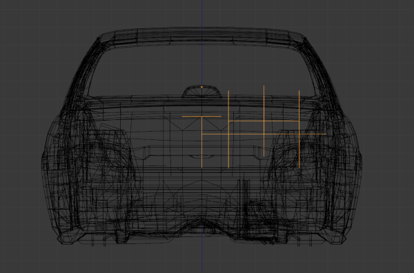
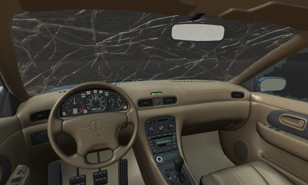
"Starting the interior of a car can be a bit daunting without any reference markings, so it’s best to draw up a series of lines marking out the the edges of the door panels and centre console first. You can use these markings to locate the steering wheel position, which dictates the position of the seats and some dashboard features."
"With this location pinned down, you can start modelling the dashboard and door panels. In many cars, the dash is symmetrical from the driver's to the passenger's side, with the exception of the gauge cluster. I typically keep a symmetry modifier on the mesh until I am reasonably happy with the overall shape, and then go about working on the unique geometry for each side. It’s also helpful to place a camera at the location of the driver’s head, so you can easily check the in-game PoV at any time."
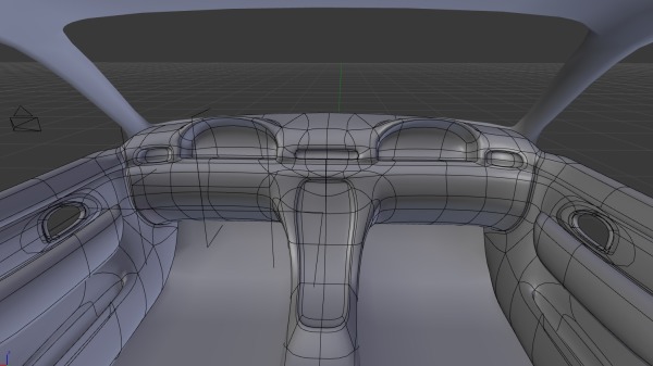
"As you can see above, I like to use subsurface smoothing (Turbosmooth for 3DS Max users) during the early modeling phase, especially with very curvy interiors like the 90s Pessima’s. This is an unconventional workflow, but can be quite helpful for guaranteeing consistent curves, assuming the base mesh is very low-poly."
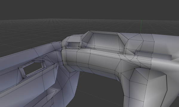
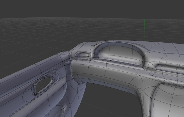
"Below, you can see the base mesh without any subsurface smoothing, with no more than about 500-600 triangles. This of course looks awful, but fortunately you won’t have to look at it if you keep the subsurf modifier visible while modeling. Instead you’ll see the nicely subsurfed mesh below it:
"The door panels can be started by extruding the existing edge loop from the external door mesh. Make sure to give the panels significant thickness to avoid clipping with the outer door mesh in a crash.
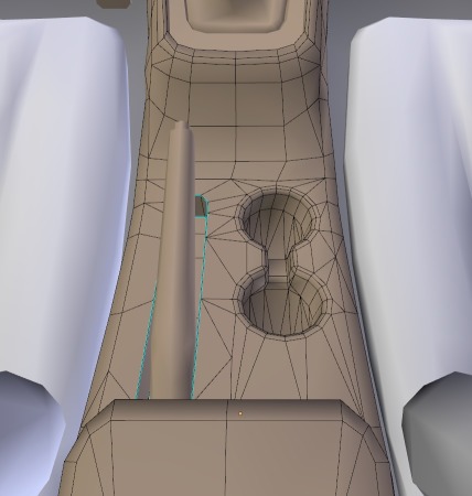
Once you’re happy with the shape, apply a single-pass subsurf modifier and watch your polygon count quadruple. You may want to merge some superfluous edge loops at this point to keep the geometry light and clean. At this point the finer details can start to be added. These include vents, door handles, knobs and asymmetrical details. As always, avoid adding geometry except where it’s needed to control shading. Some concave features like vents and cupholders need an additional ring of edges around them to avoid disturbing the shading on the main surface hosting them."
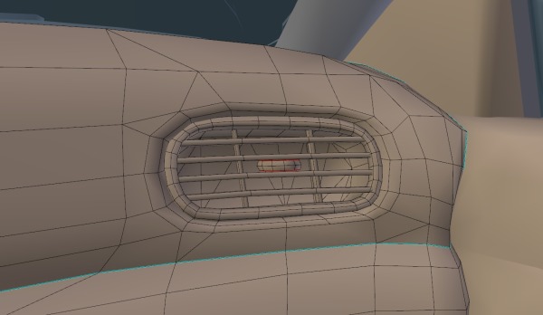
"Sometimes it’s necessary to use triangles instead of quads, but be careful that they don’t result in poor shading. Reducing geometry by merging edges can often be a more effective means for smoothing out the appearance of a model than adding polygons, and this will be especially true once a high-poly smoothed normal map is baked on."
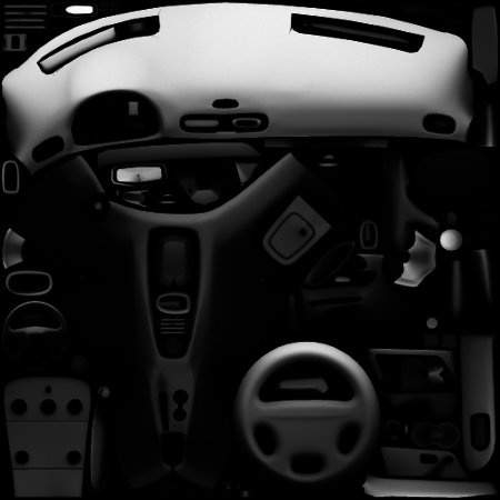
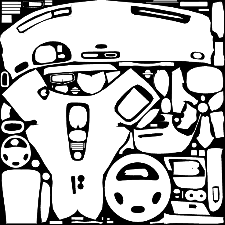
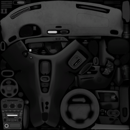
"UV mapping the interior is all about finding continuous surfaces and unwrapping them in such a way that seams are either not visible, or occur at the edges of materials. For very curvy interiors this can result in some pretty unusual UV layouts. Once the UV layout is finished, the first thing I do is bake an ambient occlusion pass onto the texture. This is a helpful starting point since it will be used in almost all of the texture layers. Bake the AO with a subsurf modifier for extra smoothness. Note that any parts that can move or rotate may look wrong with AO applied unless they are first separated from nearby occluding objects (see the steering wheel in the image below for an example – this had to be re-baked afterwards)."
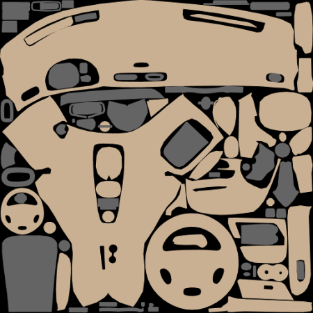
"Next, it’s a good idea to bake a colour-coded map of material types and keep it on a hidden layer in your working file, so you can easily select everything using a particular material when creating the texture.
The official cars currently use 2048×2048 interior textures, which we think is a suitable middle ground between quality and loading speed. Nevertheless, we work on textures at 4096×4096 to preserve their quality during editing, and to allow future-proofing."
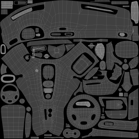
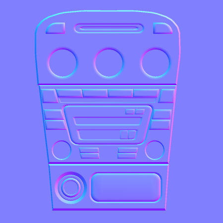
"Now bake the normal map on, also using a subsurf modifier. To give the edges of UV islands some extra pop, you can also overlay a UV island-based bevel map. Simply render out the UV islands in white (below) in very high resolution, apply some Gaussian blur and run a normal map filter to create well-defined normal map edge bevels."
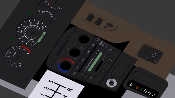
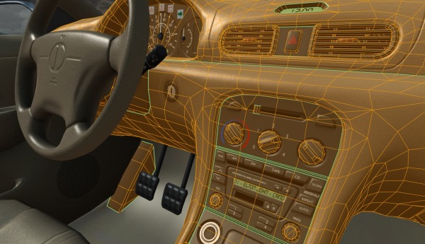
"Some details are too small to be included in the mesh geometry, but can be modelled separately and baked as normal and diffuse maps onto the main texture. I group these in a new layer and use them to bake temporary textures, before baking these textures onto the main interior textures. In Blender, you can use two UV layers to manage this: one UV layer is for the temporary detail textures (stereo, A/C unit, power window controls), and another UV layer is for the main texture, which the details will be baked to."

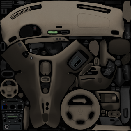
"A specular map can generally be derived from the diffuse map, with some special overlays to account for differences in materials or adding grunge spots. For a subtle lighting effect that gives the diffuse textures a photo-like quality, the normal map can be converted to greyscale and faintly applied as “hard light” over the main diffuse texture. Reflectivity is the inverse of the diffuse texture’s alpha map; more transparent areas are more reflective.
If you’re working in Blender, it’s helpful to set up the materials for preview in the viewport. However, be aware that things can look significantly different in-game, so it’s a good idea to regularly export your work to get a feel for how the lighting will look in BeamNG.drive."
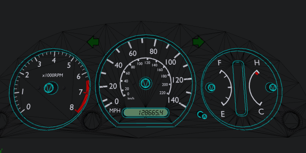
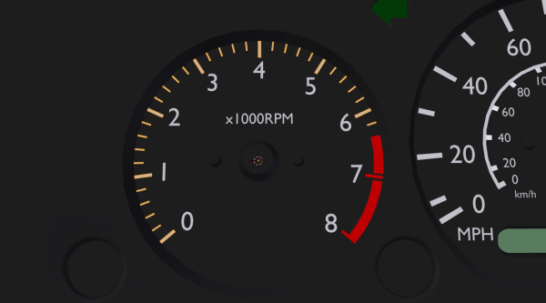
"Making the gauge cluster is more of a mathematical problem than a modeling issue, and involves first figuring out the range of the speedometer, the number of interval marks, and the total angle of the needle arc from zero to max speed. Once you’ve sorted this out, it’s a simple matter of creating a single interval mark and copying it around the perimeter of the gauge, rotating it by several degrees at a time. Keep switching back to your camera in the driver’s head position to make sure the gauges are readable. The finished gauge cluster model can be rendered onto 1024×512 textures; diffuse, normal and specular, which will then be applied to a flat plane on the dashboard mesh with a unique material."

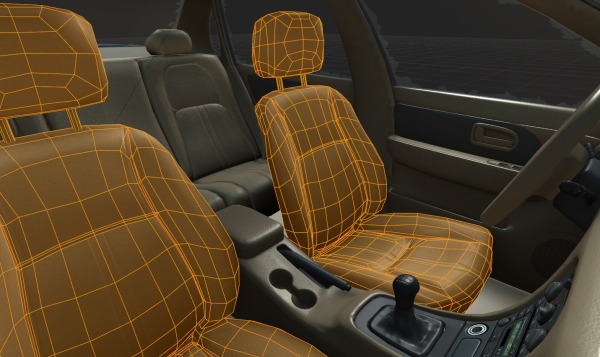
"Seats can also be modelled using the 2-stage process of low-poly primitive shapes, and application of subsurface smoothing followed by refining and cleaning up the mesh. These can be assigned their own 512×512 textures. Depending on styling (more curves usually result in more geometry), the full set of interior meshes may have up to 20,000 triangles."
"The process described above is certainly not the only way to create an interior (and I’ve probably offended a few modeling purists with my subsurf method), but should help shine some light on the task at hand. This year [in 2016], we’ve started seeing very high standards in community car mods, and I hope this helps pave the way for more fantastic user-made content."
-gabester