Introduction to Vehicle Creation
| Language: | [[::Introduction to Vehicle Creation|English]] • [[::Introduction to Vehicle Creation/ru|русский]] |
|---|
Disclaimer: The plugin used in this tutorial is now capable of exporting collision triangles from triangular faces. As long as exporting coltris is enabled, the normals on your model are correctly oriented, and all faces have been triangulated, adding coltris directly to the JBeam is not needed.
Contents
Software Tools
All of the software you need to create a fully functioning car, even one of similar quality to the official vehicles, is free. For this tutorial, I'll be using the following programs:
- Blender (3D modeling)
- Blender JBeam exporter plugin
- GIMP (texture creation)
- Notepad++ (JBeam editing)
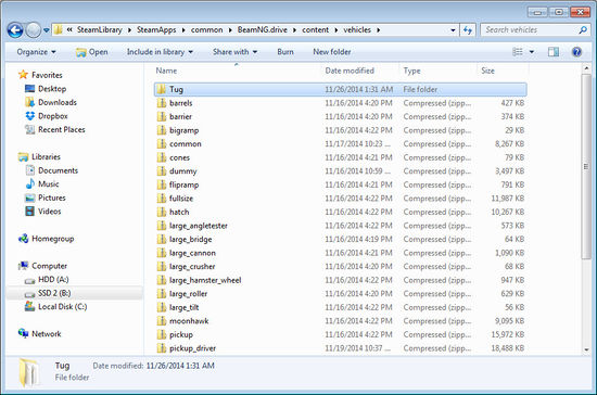
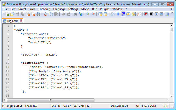
Once you have these installed, set up a folder in which to create the vehicle. This folder will go in your Steam/steamapps/common/BeamNG.drive/content/vehicles directory or your Documents/BeamNG.drive/mods/unpacked directory. Give the folder a short name which is relevant to the vehicle you're making. For this tutorial, I'll be creating a simple vehicle based on an airport tug, so I've named the folder “Tug”.
With our folder in place, we can open it up and add the all-important main JBeam file.
JBeam Setup
We'll paste the following lines of code into the new document:
{"My Car":

{
    "information":{
        "authors":"Riley",
        "name":"My Car",
    }

	"slotType" : "main",

	"nodes": [
		["id", "posX", "posY", "posZ"],
		{"nodeWeight":10},
        {"frictionCoef":0.7},
        {"nodeMaterial":"|NM_METAL"},
        {"collision":true},
        {"selfCollision":true},
	],

  "beams": [
		["id1:", "id2:"],
		{"beamSpring":2000000,"beamDamp":200},
		{"beamDeform":80000,"beamStrength":"800000"},
    ],

}
}
This is essentially the framework of a JBeam file, containing all that we need to start working on a vehicle. As you can see, there are three main sections: “information”, “nodes” , and “beams”. We'll add data to the nodes and beams sections later on, but for now you can go ahead and replace the information fields with your own author name and project name.
Although this is a valid JBeam file, it contains no data about the structure of the vehicle. To produce that data, we're going to construct a node-and-beam (n/b) structure in Blender.
Nodes and Beams
Open up Blender and edit the default cube. You can use it for a scaling reference – each side is two metres long. Bearing this in mind, delete the vertices of the cube and start adding your own by extruding (E) from other vertices or faces. Ctrl-right click or shift-right click to select multiple vertices, edges, or faces. The two fundamental components of a JBeam structure are as follows:
- Nodes have mass, but no dimensions. Nodes are represented by vertices in Blender.
- Beams connect nodes and have other physical properties like stiffness and strength. Beams are represented by edges in Blender.
Keep adding vertices and edges until you have blocked out the basic shape of your vehicle. Keep the distribution of vertices fairly even, and don't use more than a hundred or so. You can add faces to the model to make it easier to visualize, but they won't be relevant as part of the n/b structure for now (unless you decide to export them as collision triangles).
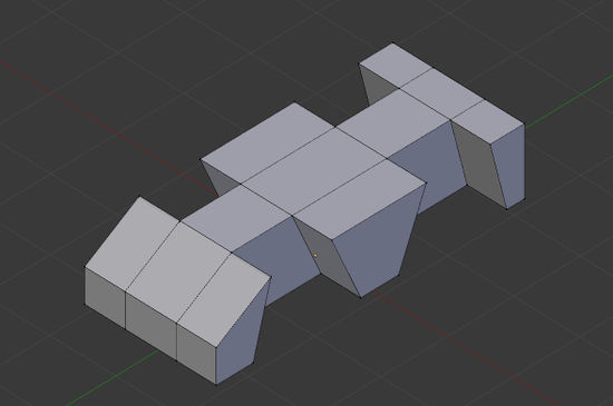
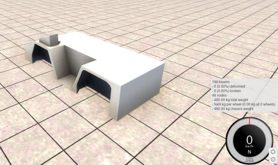
After finishing the basic body shape of my airport tug, I've only used 48 nodes. Although the shape looks correct, it won't support itself in BeamNG.drive since it has no cross-bracing beams. To fix this, we need to go back and make sure every face is crossed by two edges to provide rigidity through triangulation. To cross a face, select two opposite corner vertices and press F to create an edge between them. Alternatively, you could use the triangulate modifier (Ctrl-T).
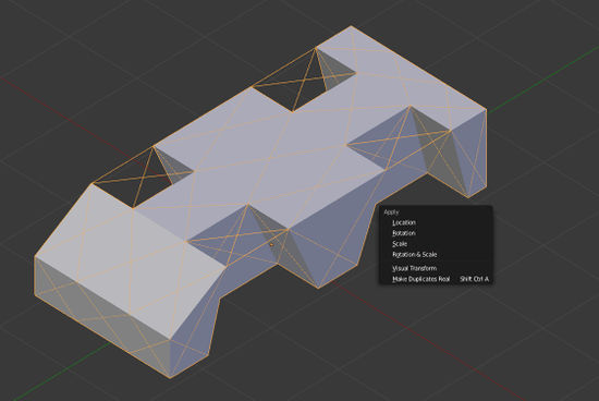
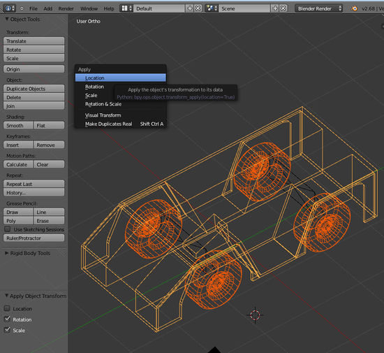
Once all the faces are crossed by two edges, you can exit edit mode and move the model just above the X-Y axis plane so that if it had wheels, they would be just touching the plane. Then apply the location, rotation and scale of the model using Ctrl-A.
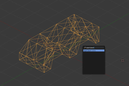
It's now time to export the Blender model into the JBeam format. For that, we need to download and install rmikebaker's script from the link above. With the script installed, configure export options under the Scene tab in the Properties menu to the right. You can now export any triangulated mesh object as an n/b structure. Select the object and export it – the file should be saved adjacent to your Blender file.
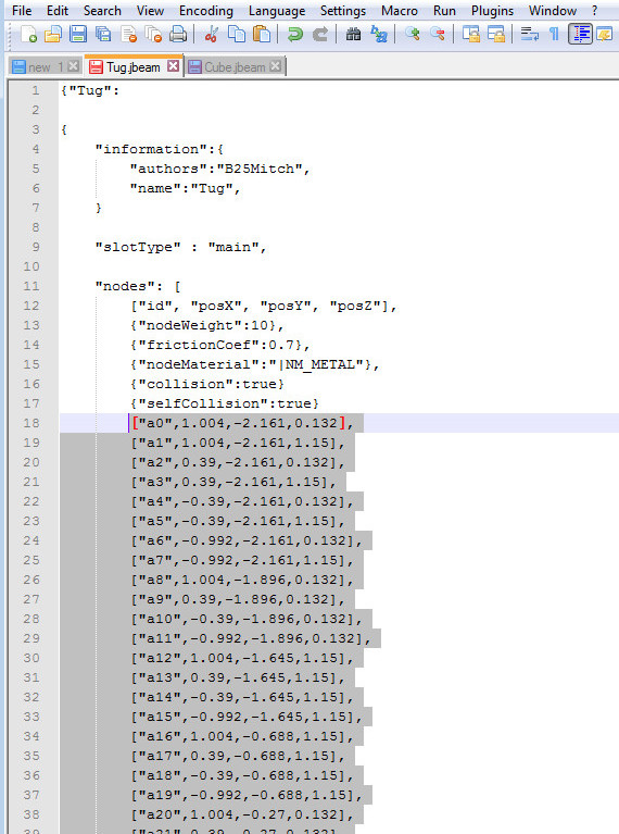
Open up the exported JBeam file and take a look. It will have the same name as the object you exported it from, so if you haven't bothered to rename the default object, it will probably be called something like Cube.jbeam.
This isn't a complete jbeam file, but it does contain the node and beam information that our previous Tug.jbeam file was lacking.
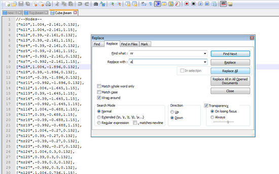
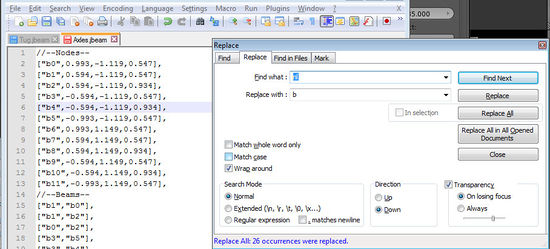
As you can see, each line defines the name of a node (vertex in Blender), followed by the XYZ coordinates of that node. The exporter has given each node a number and a prefix, either “nr” or “nl” depending on which side of the vehicle the node is on. I prefer to keep my node prefixes simple – single letters if possible – so I will use Find and Replace to change all the prefixes to the letter a. We can now copy all the lines of nodes from the Cube.jbeam file into our actual project file, Tug.jbeam. Paste them at the bottom of the “nodes” section, under the existing lines.
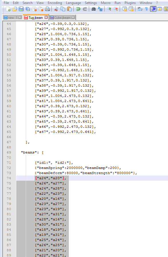
We can now do the same for the beams, which can be found under the nodes section in Cube.jbeam. There will be significantly more beams than nodes; typically, they number in the hundreds or even thousands. Paste them in the Tug.jbeam “beams” section, under the existing lines.
We're almost ready to load the vehicle in BeamNG.drive to test it out, but first we'll need to define a name to appear in the vehicle browser. To do this we'll create a small text file called info.json, and type in the following text:
{
    "Name":"Tug",
    "Author":"YourNameHere",
    "Type":"Car",
    "default_pc":"default",
    "colors":{
        "Pearl White": "1 1 1 1"
    }
}
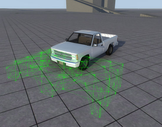
Now, with a JBeam containing nodes and beams and a name appearing in the vehicle selector, it's possible to load the vehicle in-game. Open up BeamNG.drive, go to one of the grid maps, and find your vehicle in the browser.
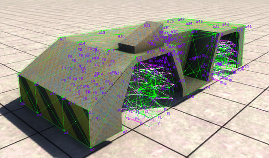
Since there's no visible model for it yet, you'll have to press K to turn on JBeam debug (or Ctrl-B to show beams) in order to actually see it. If all has gone well, the shell of the car will be fairly rigid and self-supporting. If not, you'll have to go back and add more connecting edges in Blender, re-export the JBeam and copy the revised beam section into the main JBeam file.
At this stage, only the nodes will be able to collide with other vehicles (we'll cover collision triangles later), but you may still want to try hitting the shell with things to test its strength.
You can also try adjusting the properties of the n/b structure using the JBeam file parameters. There are several values you can tweak inside the nodes and beams sections. For nodes, you can try changing the weight and friction coefficient. For beams, you may wish to adjust the beamSpring (stiffness), beamDamp (damping), beamDeform (permanent deformation threshold) and BeamStrength (breaking threshold) values. Higher spring values will result in a stiffer vehicle, but go too high and the JBeam will become unstable and explode. However, you can get away with higher spring values if you lower the damping values. beamDeform and beamStrength specify the force needed to permanently damage or break (delete) a beam, respectively. It might be a good idea to set beamStrength to infinite ("FLT_MAX") if that part of the car isn't specifically designed to break away cleanly.
Each time you make changes to the JBeam file, you need to save it and press Ctrl-R in BeamNG to reload the vehicle in place.
These are all things you can continue to tweak later, so for now, let's move on to modeling a visible mesh in Blender.
Modeling and Texturing

Blender isn't the easiest program to learn, but even a first-day novice should be able to produce a simple model like the one above using the fundamental key commands: G (grab), R (rotate), S (scale) and E (extrude) to manipulate and add geometry. Follow the key commands with a tap of the X, Y, or Z key to constrain the action to a particular axis.
You'll also probably want to add an edge split modifier to keep the smoothing groups looking nice. If it's your first model, don't stress over it too much – we're just getting a grasp of the basic skills here.
If you're reasonably happy with the shape of the model, it's time to give it a material and texture. First add a material from the materials menu and rename it to something relevant. I've called mine Tug_body.
Open up the UV image editor and create a new image with a resolution of 1024x1024 pixels. This will be our main texture. Now we'll go into edit mode, select all the faces and hit U to unwrap the texture coordinates. For best results, use "Smart UV Project", or unwrap parts one at a time with "Project From View" (using the numeric keypad to align your view). With all the faces still selected, open up your newly created texture from the UV image editor.
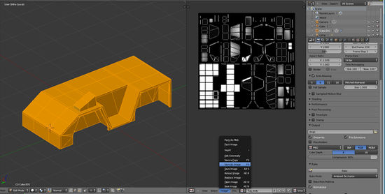
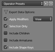
We'll use Blender's Bake function to automatically generate a simple texture. In the Render tab within the Properties menu, scroll down to Bake at the very bottom, set the Bake mode to Ambient Occlusion, and hit the Bake button. Blender will now start rendering soft shadows onto the texture we just created. Now that we have a rudimentary texture created for us, we can save it into the project folder as a .png file. It's time to export the visible mesh as well; before doing so, apply the rotation and scale, just as we did for the n/b structure. Also, name the object something sensible, like Tug_body. Select it in object mode and use File > Export > Collada (Default) (.dae). Make sure the "Apply Modifiers" and "Selection Only" presets are enabled.
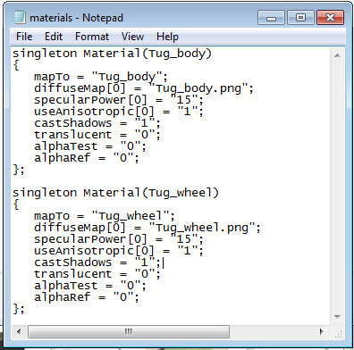
When we exported the model to a .dae file, it carried a material slot with it called Tug_body, but we need to create a Torque3D material to assign to that slot. Create a new text file in the project folder called materials.cs and paste the following lines into it:
singleton Material(Tug_body)
{
   mapTo = "Tug_body";
   diffuseMap[0] = "Tug_body.png";
   specularPower[0] = "15";
   useAnisotropic[0] = "1";
   castShadows = "1";
   translucent = "0";
   alphaTest = "0";
   alphaRef = "0";
};
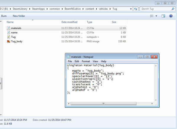
This file will be used to define all the materials on our vehicle. The "mapTo" value must have exactly the same name as the Blender material we created prior to exporting. The “diffuseMap[0]” value must be the exact name of the texture ("Tug_body.png" in this case) that we baked in Blender and saved to the project folder.
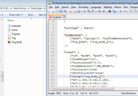
The final part of getting all this modeling and texturing work to show up in-game is defining a Flexbody mesh in the jbeam file. To do this we'll have to add a Flexbody section. A Flexbody section can be very simple, and in my case it contains the following text:
"flexbodies": [
		["mesh", "[group]:", "nonFlexMaterials"],
		["Tug_body", ["tug_body_g"]],
	 ],
The first parameter is the name of the mesh, the name we gave it prior to exporting as .dae. The second is the name of the node group to which the mesh will be attached. We don't have any node groups yet, so let's go down to the nodes section and add this line before the first node:
{"group":"tug_body_g"},
All the nodes following this line will be included in the new group tug_body_g. If at some stage you add nodes that you don't want to be part of this group, precede them with the closing line:
{"group":""},
It's finally time to see the results of all our modeling and texturing work in-game. If you've still got the level open, hit Ctrl-R to reload the vehicle and see the new flexbody mesh:
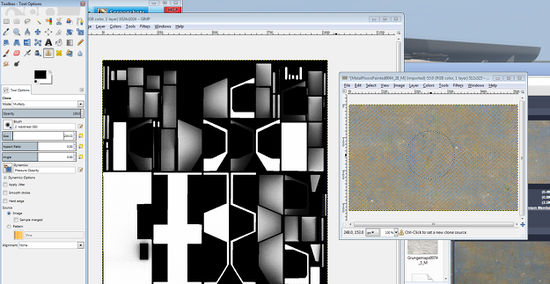
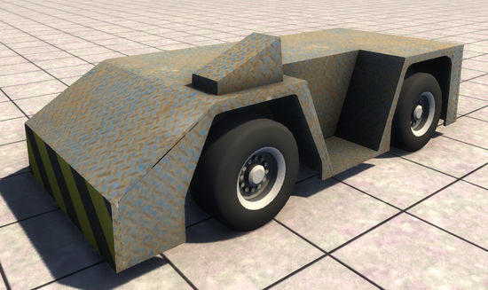
At this point you'll notice the texture is nothing special – simply some grainy shading in the corners – but that's easy to fix. Launch GIMP and open up the texture image. Add a new layer which multiplies over the base image, and find a free metal texture on Textures.com or any free texture site of your choice. Use the clone tool to paint the metal texture onto the white vehicle texture.
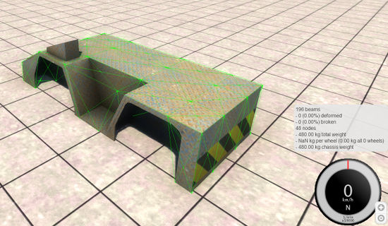
With a minute or two of work I've covered the body in a nice metal pattern and added hazard stripes to the front and rear. Overwrite Tug_body.png and hit Ctrl-R to reload the vehicle, updating the texture. You may have to clear the cache file in My Documents/BeamNG.drive/cache/vehicles or, in some cases, restart the game to force the texture to update.
Axles
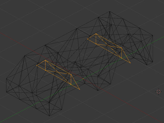
The body shell of our tug is complete, but we don't have any wheels or axles yet. To fix this, we'll go back to Blender and make a new n/b structure inside the previous one, except as a different object this time. Each axle will consist of four nodes, with an additional node on each side to hold the wheel. The beams will be set up so as to allow the single nodes on each side to hinge forwards and backwards – this will enable the wheels to be steered.
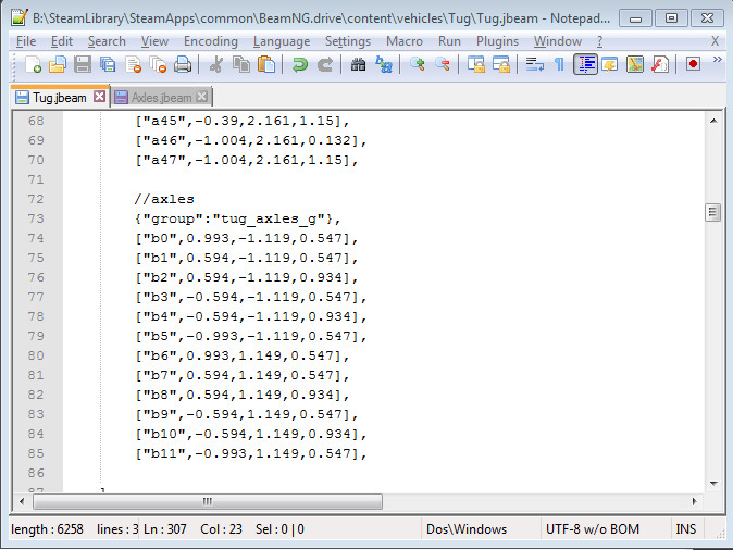
As we did with the body shell n/b structure, apply location, rotation and scale to the axle n/b structures and use the export script to output the node and beam information. This time we'll rename the node prefixes to "b", to differentiate them from the “a” prefixed body shell nodes.
Copy the nodes and beams sections and paste them into their respective sections in the main jbeam file, below the previous node or beam definitions. It's a good idea to add a comment using "//", to remind yourself what these nodes are for. You may also want to make the axle nodes part of a new group.
If you save the JBeam file and reload the vehicle, the axle will now be present and in the correct place, but not attached to anything. We'll need to attach each of the four central axle nodes to each of the four central body shell nodes under it.

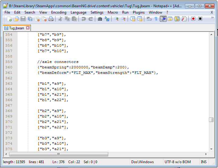
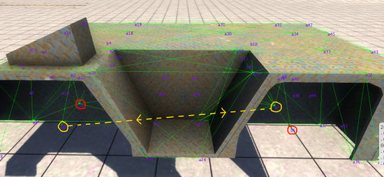
The good news is we don't have to go back into Blender to do this – we can just remember the names of the nodes and manually type beams into the jbeam file using the node names. Press L twice to display the node names. Let's start with node b1, which needs to be attached to a9, a10, a21 and a22. We'll go to the bottom of the beams section, leave a space, and then add the following lines:
["b1","a9"],
["b1","a10"],
["b1","a21"],
["b1","a22"],
We've just created four new beams linking b1 to four of the body shell nodes. Do the same for the other axle beams, for a total of 16 connecting beams on the front axle and 16 on the rear.
After reloading, the axles are firmly connected to the body shell and are capable of supporting wheels, which we have yet to add. Before we do that though, let's set up some steering while we still have a clear view of the axles.
Hydros
Because the ends of the axles are free to rotate forwards or backwards, all we need to do is to attach a beam that can expand or contract to move it around. Fortunately, such things exist, and they're called hydros.
Just like for flexbodies, we need to add a new section to the JBeam for hydros. It looks like this:
"hydros": [
        ["id1:","id2:"],
	]
Traditionally, the hydros section is placed directly under the beams section, although this isn't strictly necessary. Inside the hydros section we'll define beams by listing the start node and the end node, followed by a few parameters that control the speed and amount that the beam is able to expand or contract.
A typical hydro definition looks like this:
["b0","b7",{"factor":0.05,"steeringWheelLock":460,"lockDegrees":25}],
We'll leave steeringWheelLock and lockDegrees at their default values for now, because what we're really interested in is the factor value. This parameter will determine whether the beam expands or contracts (depending on whether it is positive or negative), and the value determines the length of contraction or expansion that is allowed. It is usually a good idea to give hydros a lower spring value and more damping than the surrounding beams, to avoid super-powerful hydros which might warp the frame of the vehicle.
With one hydro for each wheel, all four wheels are now steerable. To test it out, reload the vehicle and move the steering controls.
Wheels
Disclaimer: The HubWheels wheel model has been deprecated since version 0.3.7.4. Using PressureWheels instead is highly recommended.
Now that steering is working, it's time to put wheels on the axles. Wheels are automatically generated from two nodes in the hubWheels section of the jbeam. However, they also come with a whole lot of parameters that can be adjusted, most of which are self-explanatory with some knowledge of real-life car wheels, in addition to the familiar n/b properties such as nodeWeight and beamSpring.
A hubWheels section may look like this:
"hubWheels": [
        ["name","group","node1:","node2:","nodeS","nodeArm:","wheelDir"],
        {"enableTireSideSupportBeams":true},

        //general settings
        {"radius":0.47}, //Radius of the tire nodes
        {"hubRadius":0.25}, //Radius of the rim
        {"wheelOffset":0}, //Offset from the original position(Left/right)
        {"hubWidth":0.4}, //Width of the rim
        {"tireWidth":0.4}, //Width of the tire
        {"numRays":12}, //The amount of nodes to make the circle, more may result in smoother driving, but at the cost of performance, weight & stability

        //hub options
        {"hubBeamSpring":1081000, "hubBeamDamp":16},
        {"beamSpring":1081000, "beamDamp":16},
        {"hubBeamDeform":36000, "hubBeamStrength":112000},
        {"beamDeform":240000,"beamStrength":380000},
        {"hubNodeWeight":0.60}, //Weight of the rim nodes, to get the total weight of the rim, calculate numRays X nodeWeight X 2
        {"hubNodeMaterial":"|NM_METAL"},
        {"hubFrictionCoef":0.7},

	//tire options
        {"wheelTreadBeamSpring":281000,"wheelTreadBeamDamp":90,"wheelTreadBeamDeform":25000,"wheelTreadBeamStrength":34000},
        {"wheelPeripheryBeamSpring":281000,"wheelPeripheryBeamDamp":90,"wheelPeripheryBeamDeform":25000,"wheelPeripheryBeamStrength":34000},
        {"springExpansion":1081000, "dampExpansion":18},
        {"nodeWeight":0.60}, //Weight of the tire nodes, to get the total weight of the tire, calculate numRays X nodeWeight X 2
        {"nodeMaterial":"|NM_RUBBER"},
        {"frictionCoef":1.1}, //Tire friction for each node, increasing will add more grip to your vehicle
        {"pressurePSI":30}, //Tire pressure in PSI
        {"maxPressurePSI":1500},
        {"reinforcementPressurePSI":30},
        {"pressureSpring":2601000},
        {"reinforcementPressureSpring":144000},
        {"pressureDamp":90},
        {"reinforcementPressureDamp":90},

        //front
		{"propulsed":0}
        {"selfCollision":false}
        {"collision":true}
        {"axleBeams":["b3","b1",]}
        ["FL", "wheel_FL_g", "b0", "b1", 9999,  "b2", 1],
        {"axleBeams":["b3","b1"]}
        ["FR", "wheel_FR_g", "b5", "b3", 9999,  "b4", -1],
        {"axleBeams":[]}
        {"enableABS":false}
        {"selfCollision":true}

	//rear
		{"propulsed":1}
        {"selfCollision":false}
        {"collision":true}
        {"axleBeams":["b7","b9",]}
        ["RL", "wheel_RL_g", "b7", "b6", 9999,  "b8", 1],
        {"axleBeams":["b9","b7"]}
        ["RR", "wheel_RR_g", "b9", "b11", 9999,  "b10", -1],
        {"axleBeams":[]}
        {"enableABS":false}
        {"selfCollision":true}
	],
At the very end of the section the wheels themselves are created from two nodes on the axle, plus a third node away from the center that acts as the application point for torque. A single wheel definition inside the hubWheels section looks like this:
["FL", "wheel_FL_g", "b0", "b1", 9999, "b2", 1],
The first parameter Is the name of the wheel. The second is the name of the node group (for attaching flexbodies). The third and fourth parameters are the two host nodes that run through the center of the wheel. The fifth parameter is not normally used and may be left at 9999, the sixth parameter is the node used for torque application (where the brake pad would be), and the final parameter controls the wheel direction.
Wheels can be very different depending on the vehicle, and yours will likely need a lot of changes to fit your particular car. The parameters above have been tuned to fit the tug and result in large diameter, thick wheels.
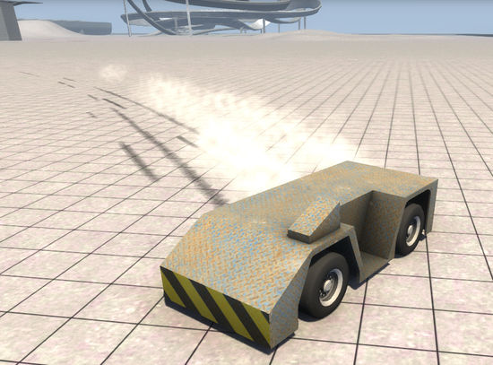
Once you've added wheels, you can reload the vehicle in-game and try rolling it down a hill or pushing it around with another vehicle, although it'll look like something out of Star Wars until we model some visible wheels for it.
To do that, let's go back into Blender and add a new object for the front-left wheel, based on a circle with 32 vertices. We can extrude and scale the circle into a convincing wheel profile, and then add smaller, 8-vertex extruded circles for the wheel nuts. After adding a unique material and creating a texture using the same method as for the body, we've finished the first wheel. Now just copy the wheel object three times and rotate the duplicates into their positions. Give each wheel object an appropriate name, such as WheelFL. Select all the wheels and apply location and rotation/scale, before re-exporting all the visible meshes to the .dae in the project folder.
Since we'll need a different material for the wheels, let's open up that materials.cs file we created earlier and define a similar material that uses the wheel texture as its diffuse map. Remember to change mapTo to the name of the wheel material in Blender.
To attach these mesh wheels to the JBeam wheels, just expand the flexbodies section to include new lines listing the wheel mesh name and corresponding node group (defined in the hubWheels section).
Clear the cache and restart the game. Your model should now be visually complete with textured wheels. If the wheels wobble or orbit the axles when they rotate, go back into Blender and check that the wheel meshes are aligned. Make adjustments to the wheel position, reapply location, rotation and scale, and re-export. If you haven't manually adjusted the locations of the axle nodes since you exported them, you can just line up the wheels with the axle nodes to ensure the mesh is centered.
Engine and Transmission
There is only one step left to make the car drivable, and that involves adding an engine and transmission. Like hubWheels, an engine section contains a lot of unique parameters, most of which correspond to real-life engine properties. These are best explored by experimenting on your own, so for now, use the code for the Ibishu Covet's engine and transmission to make the wheels turn. Usually, the engine section will go above the nodes section. The torque should be comparable to that of an everyday economy car, and should not reach levels like 850 unless you know exactly what you're doing.
"enginetorque":[
        ["rpm", "torque"] //Torque curve
        [0, 0],
        [500, 60],
        [1000, 73],
        [2000, 93],
        [3000, 115],
        [4000, 132],
        [4500, 134],
        [5000, 135],
        [6000, 134],
        [7000, 114],
        [7500, 90],
    ],
    "engine":{
        "idleRPM":1000, //Idling RPM
        "shiftDownRPM":3400, //Downshift, for automatic
        "shiftUpRPM":6400, //Upshift, for automatic
        "maxRPM":7500, //Maximum RPM for the engine (redline)
        "inertia":0.08,
        "friction":16,
        "brakingCoefRPS":0.15
        "burnEfficiency":0.5
        "throttleSensitivity":1.2

		//transmission section
		"transmissionType":"manual", //Automatic or manual; the automatic setting will restrict the use of manual mode while playing
        "lowShiftDownRPM":1400,
        "lowShiftUpRPM":3600,
        "highShiftDownRPM":3300,
        "highShiftUpRPM":6000,
        // -1, 0 (neutral), 1, etc
        "gears":[-2.9, 0, 26.5, 13.25, 8.82, 6.625] //Gear ratios
        "clutchDuration":0.25
        "viscousCoupling":3.5
        "lockingTorqueLimit":150
        "enableLocking":true
        },
For my tug, I've changed the gear ratios significantly since it has such large wheels – you may have to make changes as well, depending on the type of vehicle you are creating.
At this point, my vehicle is fully drivable, but without suspension, the ride is pretty nasty and rear steering makes it prone to spinning out. These are problems that could be solved with a decent suspension setup, but that's beyond the scope of this already lengthy tutorial.
Reference Nodes
You may have noticed by this stage that the external camera doesn't behave quite like it should. This is because we haven't yet added reference nodes. Let's do that now.
Reference nodes let the camera know which direction the vehicle is pointing, and also establish a central point when reloading the vehicle.
There should be four reference nodes arranged in a right-angle tetrahedron pattern. The section looks like this:
"refNodes":[
        ["ref:", "back:", "left:", "up:"]
        ["ref0", "ref2", "ref1", "ref3"]
    ],
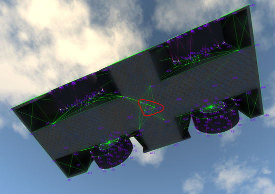
For it to work, we need to create nodes with corresponding names in the nodes section. That is, we need to create a node at [0, 0, 0], a node directly behind it, a node directly to the left and a node directly above. We could go back into Blender to model and export the reference nodes, but it's not too hard to figure out what the coordinates should be in your head. In my case, they will look like this:
		["ref0",0.0,0.0,0.0],
		["ref1",0.2,0.0,0.0],
		["ref2",0.0,0.2,0.0],
		["ref3",0.0,0.0,0.2],
This results in a neat triangular pattern of reference nodes just under the vehicle. Connect the reference nodes to the body shell with beams, with the same method used to attach the axles.
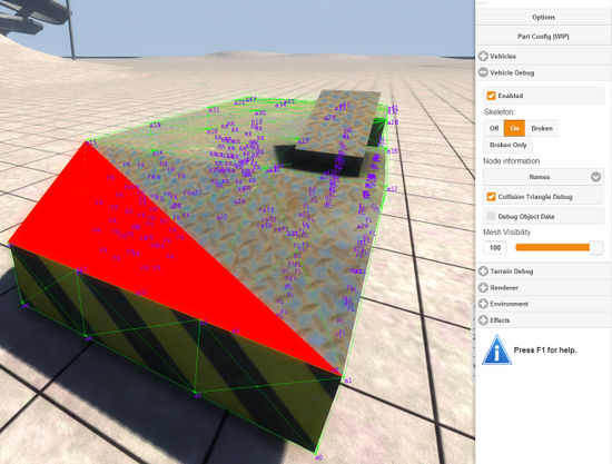
Collision Triangles
Collision triangles, aka "coltris", are an essential part of inter-vehicle collisions. Beams cannot collide – only nodes are capable of collision detection, and only coltris can collide with nodes. Without coltris, an attempt to crash two tugs together would result in them passing straight through each other.
To create coltris, we will set up a new section at the end of the jbeam file, called "triangles".
"triangles": [
		["id1:","id2:","id3:"],
		{"dragCoef":10},

],
Inside the triangles section, we can create coltris by listing their three surrounding nodes. The nodes should be listed in a counterclockwise direction in order for the coltri normal to point outwards (resulting in more reliable collision detection).
As an example, a triangle looks like this in the JBeam:
["a15","a7", "a1"],
Creating triangles manually is a tedious task, and covering an entire vehicle can take a few hours. Don't take shortcuts, though; make sure the vehicle is fully surrounded by triangles or you may end up with undesirable clipping errors in collisions.
Conclusion
There are many more elements involved in creating a complete vehicle, including props, cameras, lights, break groups, deform groups, and, of course, suspension, but with the basic skills learned from this tutorial you should be capable of grasping those concepts with the help of the relevant wiki pages.
You can respond to us with your feedback in this thread.
| Vehicle Creation | ||||||||||||||||
|---|---|---|---|---|---|---|---|---|---|---|---|---|---|---|---|---|
| Get started: Introduction to Vehicle Creation | ||||||||||||||||
| ||||||||||||||||
| See also: JBeam Examples • JBeam Physics Theory |