Construction Guide
This page will outline some general tips and the basic workflow for creating a structure with nodes and beams.
Contents
Starting out
It's best to have a 3D model that's well progressed before beginning work on the physics structure. The underbody, suspension, frame, and similar elements should already be modelled.
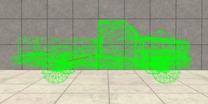
For the most part, a vehicle's structure will consist of a grid-like latticework of nodes and beams. The spacing of these nodes is a balance between resolution and performance, while also minimizing the distance between nodes—which static objects can pass through. Nodes should be placed to match the shape of a mesh - the mesh and its corresponding structure are in the same coordinate space (in meters). Equal spacing should be strived for if possible.
Frame
For something like a vehicle's floor, it can be easily built with just two congruent grids of nodes, one above the other. First create the beams making the basic shape—that is, the ones making the "grid." Make them in all 3 axes: from side to side, front to back, and vertically.
This structure alone won't hold itself up, so the next step is to add the crossing beams. For every rectangle created by 4 nodes and 4 beams, there should be 2 beams crossing the surface to rigidify it. The key to rigidifying any structure is triangulation, so these crossing beams are effectively triangulating it twice. Again, this should be done in all 3 directions. At this point the structure will hold itself up, though it will probably flex more than is desired. At this point, extra rigidifying beams can be added where needed. Lengthwise and widthwise, it helps to connect every other node (as opposed to adjacent nodes).
It's also important to set deformation values properly. The main shape beams should be reasonably strong—the structure should bend, not shrink (in most cases). It varies a lot based on how a structure should deform—for example, there are situations where it is desirable for the structure to compress when deformed. For example, the floor of a real-life vehicle is made up of several sheets of stamped metal, which can crumple quite a lot locally. This is best abstracted with easily deformed beams (since there should not be much macro bending, but more localized crumpling). The crossing beams should be a little weaker than the main shape beams, and the extra rigidifying beams should be weaker than the crossing beams.
Spring and damping values are both extremely important (and quite difficult to tune). For a given node weight, there is only so much stiffness that can be achieved before a structure becomes unstable and crashes the engine. As a result, tuning spring and damping values (and weight as well) is a fine balancing act of achieving the right stiffness without overstepping the limits of the simulation. Generally, spring values will range in the millions, while good damping values will be in the hundreds.
Once the floor is built, the next step would be to build things like the firewall, pillars, and roof. Nodes should be placed matching the mesh. It's not always necessary to give a beam structure thickness; take a look at some of the official BeamNG vehicles to see how we've constructed them. The rigidifying beams play a huge role here. These beams basically span the corners of openings to rigidify the structure without "cheating" (as in placing a beam across the entirety of a doorway). Always avoid beams that unrealistically span gaps. Instead, work around the corners of a door opening or window opening and use as few beams as possible. A "hollow" structure will always deform more realistically than one that's filled in with "cheating" beams. The inside of a car's passenger compartment is empty (other than nonstructural elements like the seats and dashboard), so the physical construction should reflect that.
The same goes for the engine bay or trunk. Look at the structure of a real vehicle, and only build what's actually there. The inner fenders of most modern unibody cars are quite thin and flimsy, and the engine bay itself is totally hollow.
Suspension
Suspension is a hugely important part of a car, the most difficult to get right, and the most rewarding to build successfully. There are a plethora of suspension setups in real life, all of which can be accurately simulated. (Slidenodes can be used to replicate a MacPherson strut setup.) Real suspensions are simply rods connected by joints, so any geometry can be represented.
Nodes should be placed at all of the various pivot points. These axis point nodes, as they'll be called, should attach to nearby chassis or frame nodes, again using a minimal number of beams to avoid over-rigidification (compromising crash behavior). More nodes are needed for things such as the top and bottom of the shock/spring assembly, the upper and lower ball joints, and finally, the two axis nodes for the wheel itself. A rigid spindle structure should be formed including these axis nodes, with its camber and toe determined by control arms and other components. There will be a more detailed look at various suspension setups and how to construct them in another article. The beams creating the control arms and spindles should be as stiff as possible. It can be very challenging just to make the suspension components rigid enough to withstand hard cornering without buckling or vibrating.
Engine and transmission
The engine can be built very simply as just a cuboid (8 nodes) with rigid beams interconnecting all 8 nodes to each other. Another node can be added to represent the end of the transmission where it would connect to the driveshaft in a longitudinal setup.
From there, the engine mounts (which are often quite soft on a real car) can be built, again using minimal beams. A real car's engine has quite a lot of freedom to rock around. Here, support and bounded beams come in handy to prevent clipping and simulate the self collision of the engine block with other parts of the vehicle's structure.
Body panels
Once the main structure of the vehicle is built, it's time to add detaching body panels. Broken down to its most basic elements, a body panel structure is a grid, with crossing beams and rigidifying beams (much like the floor of the vehicle) but with no thickness. Instead, one floating rigidifying node close to the structure and attached to all of its nodes with easily-deformed beams gives the panel sufficient rigidity without having to use as many nodes. In most cases, this node should not collide with anything.
The main shape "grid" beams on a body panel should be very strong, since the panel should bend, not shrink.
Once the panel is working by itself as a self-contained rigid structure, it's time to attach it to the car. In most cases there will be two components - a hinge and a latch. For the hinge, two pivot points will need to be used to lock the structure's rotation to one axis. These can be nodes on the panel itself, or on the underlying vehicle structure.
The latch should just be a few beams to neighboring chassis nodes - again, just enough to hold it there rigidly, and not too many.
Support beams are hugely important here. They should be added for just about every possible case of self-collision. Give them fairly high deformation and strength values. They should do their job to simulate self-collision, but also still allow the structure to crumple. Care needs to be taken to ensure the support beams do not restrict rotation of the part once the latch has broken. In this case, using precompression (with a value below 1) to allow some compression for support beams can be useful.
Beam strength
Beam physics are not very well suited to ripping/tearing materials. It's best to have infinite beamStrength values in many cases (use "FLT_MAX" instead of a huge number) to avoid unrealistically breaking parts of the structure with strange flopping or giant missing polygons. Breakable beams are great for parts that can detach, but the beams making up the main shape of something should be (nearly) unbreakable in most cases.
See also
| Vehicle Creation | ||||||||||||||||
|---|---|---|---|---|---|---|---|---|---|---|---|---|---|---|---|---|
| Get started: Introduction to Vehicle Creation | ||||||||||||||||
| ||||||||||||||||
| See also: JBeam Examples • JBeam Physics Theory |