JBeam Introduction
| Language: | [[::JBeam Introduction|English]] • [[::JBeam Introduction/de|Deutsch]] • [[::JBeam Introduction/ru|русский]] |
|---|
Contents
Introduction
This tutorial is meant for the user to understand the basics of a jbeam file. After reading, one should be able to understand and create a simple jbeam file. Here the basics, nodes, beams and triangles/quads are explained. Lots of more complicated stuff is explained in other wiki pages, one should read those as well to have a fully understanding of the all possibilities.
The JBeam_Reference page for example shows a lot more possibilities per section, and at the Content Creation page there are lots of links to pages with a more throughout explanation.
It is preferable to have a jbeam open next to this tutorial to be able to see the parts explained applied. The way the nodes and beams are set up is based on how the official parts are set up, there may be many ways to set up a jbeam. The official vehicle files can be found at "...\steamapps\common\BeamNG.drive\content\vehicles".
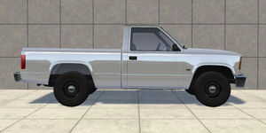
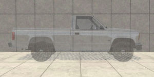
What is a jbeam? A jbeam basically is the skeleton of a vehicle. The car you see on screen is the called 'flexbody' (sometimes also referred as 'mesh') and is together with the materials and textures nothing more than the visual part of the vehicle, a bit like your skin is the visual part of your body. The jbeam is the skeleton; it defines how strong parts are, how they move, behave, when they break etc. It is a very simple text file which can be opened by using a text editor like notepad or notepad++.
This skeleton is defined by a number of location determined nodes, and are connected to each other by beams. Those beams can only withstand normal forces - push and pull forces - so a beam can rotate in all directions around a node. Compared with a real skeleton; the node is a joint and a beam the bone in between two joints.
The Basics
First if you are using a file explorer and look at the files in a vehicle folder, you'll see .jbeam, .json, .dds, .pc among other files. We're interested in the .jbeam files. For clarification purposes, we will call the filenames of the jbeam files 'jbeamfile names' and the jbeams itself the 'jbeam names'. There can be multiple jbeams inside a single jbeam file.
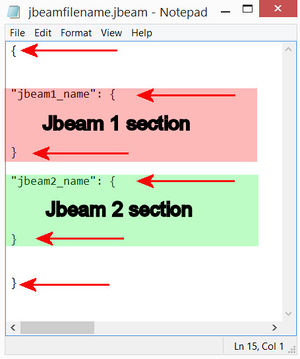
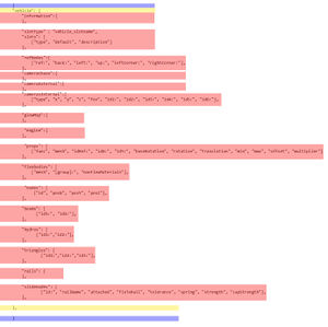
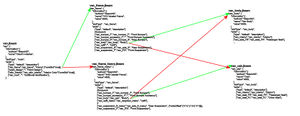
For the program to see the different jbeams and jbeam sections '{' starts a jbeam or a section, '}' ends one. This is very important to do right, otherwise the vehicle will be broken. The first image shows how a jbeam file containing two jbeams could look like, notice the brackets. The second image shows show a jbeam file could look like containing a single jbeam which has different sections. The start and end bracket of the jbeam file is blue colored, the jbeam start and end bracket is yellow colored and the different jbeam sections are red colored. Again, notice all the brackets. All sections, except for the 'rails' and camera sections, start and end with a '[' and ']' respectively. Furthermore, every line need to be ended with a comma.
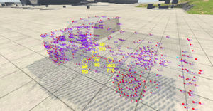
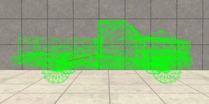
While in-game; one can see the jbeam skeleton by pressing 'CTRL N' to show the nodes, pressing 'CTRL B' to show the beams and pressing 'CTRL T' to show the triangles. One can press 'CTRL +' or 'CTRL -' to increase or decrease the visualization of the flexbody. This can be useful to clearly see how a jbeam is built.
For a jbeam to function, only the information section and slotType need to be present. All other sections are optional. So a jbeam can consist of only showing a Flexbody without added nodes and beam e.g. (in this case the flexbody should use the nodegroup of another part
Information section
"van_body": {
    "information":{
        "authors":"BeamNG",
        "name":"Van Body",
        "value":8000,
    }
This is the information section. The "van_body" is the jbeam name, the author is made clear, the 'screen name' (the name which appears in the parts selector) and the value. The latter one is a fictional value for a still-to-released buy and sell function of BeamNG.
SlotType and slots section
More possible values and options can be found in the jbeam reference page
    "slotType" : "main",
    "slots": [
        ["type", "default", "description"]
        ["van_frame","van_frame", "Frame",{"coreSlot":true}],
        ["paint_design","", "Paint Design"],
        ["skin_interior","van_skin_interior", "Interior Color"{"coreSlot":true}],
        ["van_mod", "", "Additional Modification"],
    ],
The slotType and slots section are related to each other, although the slotType is mandatory to be present, the slots section isn't.
Every vehicle needs to have a 'main' slot. BeamNG searches through a vehicle's folder for this 'main' jbeam, and starts 'building' the vehicle from there. Once a main jbeam is defined, one can add parts by using slots. As explained in the jbeam itself, the slotType of the following part is in the first part, the (optional!) default name of a jbeam is defined in the second part and the last part is the name which appears in the parts selector in-game. The optional coreSlot part means that a part must be chosen, there won't be a 'empty' option in the parts selector. There can also be a nodeOffset function:
["van_suspension_R_heavy","van_axle_R_heavy", "Rear Suspension", {"nodeOffset":{"x":0,"y":0.5,"z":0}}],
Which moves the entire jbeams in that slot. E.g. it is being used on the van and on the pickup, the latter one the extended frame rear section is just like the regular frame's rear section but moved backwards. The bed is exactly the same for both frames (including attachment nodes!), the only difference is the position.
refNodes Section
More possible values and options can be found in the jbeam reference page
    "refNodes":[
        ["ref:", "back:", "left:", "up:", "leftCorner:", "rightCorner:"]
        ["fr9", "fr10", "fr9l", "fr11", "f7ll", "f7rr"],
    ],
The reference nodes section must be present in at least one jbeam of the vehicle at all times, so including when no other part is selected except for the main (often frame or body) jbeam, so it is advisable to have it in the main jbeam (or frame/body jbeam is there's a coreslot).
- It defines the axis of the vehicle. This way the program knows what the location and rotation is of the vehicle.
- The section is also used by the external camera's, those are by default aimed at the refnode, located with a distance from the refnode in the direction of the 'back' node.
- These nodes trigger a checkpoint when driven trough it.
- These nodes are being used by the A.I.
Camera section
Like the refNodes section, the camerachase and external camera sections must be present in at least one jbeam of the vehicle at all times, so including when no other part is selected except for the main (often frame or body) jbeam, so it is advisable to have it in the main jbeam (or frame/body jbeam is there's a coreslot).
The cameras are by default aimed at the refnode, located with a distance from the refnode in the direction of the 'back' node.
    "cameraChase":{
        "distance":6.1,
        "distanceMin":2,
        "defaultRotation":{"x":0,"y":-11,"z":0},
        "offset":{"x":0, "y":0.65, "z":1.60},
        "fov":65,
    },
    "cameraExternal":{
        "distance":6.1,
        "distanceMin":2,
        "offset":{"x":0, "y":0.65, "z":0.56},
        "fov":65,
    },
Here in the refnodes section the first node is the center node (refnode), the second directly behind etc. Just like the explanation in the section itself. In the camera sections the default distance of the camera to the refnode, the minimal distance, the default rotation and offset are defined.
Ropables
This section is under development, it's for a future feature ;)
Glowmap
    "glowMap":{
            "van_signal_L":{"simpleFunction":{"signal_L":0.49,"lowhighbeam":0.49}, "off":"van_lights", "on":"van_lights_on", "on_intense":"van_lights_on_intense"},
            "van_signal_R":{"simpleFunction":{"signal_R":0.49,"lowhighbeam":0.49}, "off":"van_lights", "on":"van_lights_on", "on_intense":"van_lights_on_intense"},
            "van_taillight_L":{"simpleFunction":{"signal_L":0.49,"brake":0.49,"lowhighbeam":0.49}, "off":"van_lights", "on":"van_lights_on", "on_intense":"van_lights_on_intense"},
            ...
    },
This section defines which materials can 'glow' when a function is enabled. Take the first line of the example in the glowmap section. First the material "van_signal_L" is defined, which is actuated by two functions; the "signal_L" (which logically means if the left signal is enabled) and the "lowhighbeam" function which means that it is enabled when the lowbeam but also the highbeam is activated. The numbers following the functions mean the how much glow is enabled. The rest of the line defines which material is activated when none of the functions are enabled, when only one is activated and when both are activated.
Engine
This section is beyond this introduction, further info can be found on this Wiki page: Engine. In short in this section it is defined which break- or enginegroups are triggered in case there on of the functions is triggered. E.g. it defines which group triggers the disability of the engine in case of water intake.
Flexbody
Here is defined which Flexbody should be used and to which nodes it belongs. A Flexbody should be assigned to at least three nodes; less than three it hasn't got enough reference to be referenced to all axis (x,y,z). Also, the nodes must be about the same size and shape compared to the Flexbody. A few nodes close together for a large Flexbody will result in a 'VY error', just like having nodes close or at a axis. BeamNG needs enough reference in all three directions. To assign nodes to a Flexbody, nodegroups are being used. How to assign nodes to nodegroups is explained in the next section. A Flexbody needs at least one nodegroup, but can have more.
    "flexbodies": [
         ["mesh", "[group]:", "nonFlexMaterials"],
         ["van_body", "van_framefront", "van_framecab", "van_rearshocktop", "van_framerear", "van_cab", "van_body", "van_firewall", "van_frontmeat", "van_lowermounts", "van_uppermounts", "van_shocktop"]],
A deformgroup can be used to change the material when a certain deformgroup (defined in the jbeam section) is triggered. In the following example the "van_chmsl" Flexbody changes material from "van_lights" to "van_light_dmg" when the deformgroup "van_chmsl_break" is triggered. Don't forget to end this deformgroup!
         {"deformGroup":"van_chmsl_break", "deformMaterialBase":"van_lights", "deformMaterialDamaged":"van_lights_dmg"}
         ["van_chmsl", ["van_body"]],
         {"deformGroup":""}
     ],
To be able to move a Flexbody when a nodeoffset is used in a previous slot, one has to add a pos(0,0,0) line after the Flexbody. If you enter a non-zero value it is also possible to move a Flexbody compared to the original position in the .dae.
["pickup_taillightframe_L", ["pickup_framebed","pickup_bed"],[],{"pos":{"x":0.0, "y":0.0, "z":0.0}}],
Props
The props section is very similar to the Flexbody section; with the exception that props can move with the nodegroup (pedals e.g.) or are so called spotlights (the 'shining' part of a headlight e.g.). More exact explanations are beyond the scope of this introduction, they are explained on the Props Wiki page
How to aim a spotlight can be found in the Spotlight Positioning Wiki page
Nodes
More possible values and options can be found in the jbeam reference page
example
    "nodes": [
         ["id", "posX", "posY", "posZ"],
         {"selfCollision":false},
         {"collision":true},
         //front of frame bottom
         {"frictionCoef":0.5},
         {"nodeMaterial":"|NM_METAL"},
         {"nodeWeight":12.5},
         {"group":"van_framefront"},
         ["fr1r", -0.44, -2.03, 0.48],
         ["fr1", 0.0, -2.03, 0.48],
         ["fr1l", 0.44, -2.03, 0.48],
         ["fr2r", -0.44, -1.74, 0.48,{"group":"van_framefront","van_swaybar_F"],"chemEnergy":200,"burnRate":0.3,"flashPoint":200,"specHeat":0.1,"smokePoint":150,"selfIgnitionCoef":false}],
         ["fr2", 0.0, -1.74, 0.48],
         ...
         ],
In this section the node section is explained. A node is like a joint in a skeleton; the beams are attached to the node and can rotate around them. The nodes define the weight of the vehicle. In the example you'll see how to define the nodegroup; by adding a single line or directly behind the node line. This way one can assign multiple node groups to a node. With selfcollission one can choose if it can collide with other nodes and triangles of this vehicle, with collision if it can collide with other cars, other objects and the heightmap. Frictioncoef defines how much friction it has when it hits another object, and the nodematerial how it reacts when it hits something else. Metal can produce sparks e.g. The names and values after this group name is more complicated and are explained in a different wiki page. Important is to know that two nodes with enabled selfcollission can't be located too close to each other, failing to do so can result in unforeseen vibration and unstable behavior. A safe distance is a minimum of three centimeters between two nodes.
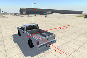
A single node has a position in the x, y and z direction. In BeamNG, all vehicles have the x in the width, the Y in the length and z in the vertical direction.
The vehicles in BeamNG are designed with the center directly in between the wheels, so the wheels are at the same y distance from the zero position. A value less than zero means it's in front of the zero position, a value larger than one means its after the zero position.
Obviously the zero position of x is in the symmetrical line of the vehicle, with everything on the right (seen from above) having a value smaller than one and everything on the left a value larger than one.
The zero position of the z axis is less obvious, the position value is taken.
Naming a node it is important to know that a name can only be used once; if a other jbeam following this jbeam has the same node name the last one will be used.
It saves lots of time to use logical names, in the above example it is logical the nodes are for the frame and one can clearly see which nodes are used for which side of the vehicle.
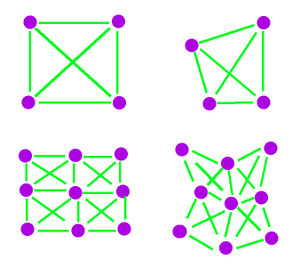
To find the number and position of the nodes. It is obvious to have a node the location where a suspension A-arm is attached to the body, but where to put it on for example a hood one has to decide how detailed the vehicle should bend or let beams rotate around. BeamNG has to calculate the location of node 2000 times a second, so the more nodes the more strain on the cpu.
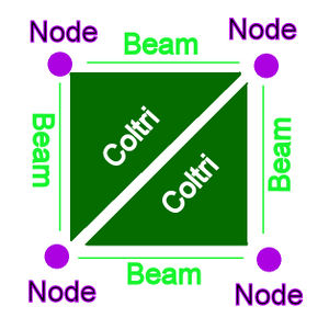
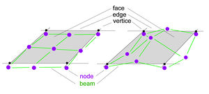
For a flat squire plate, one could have a node at each corner like example drawn in the image. Although the object can bend, it can't have any dents in between those nodes. Adding nodes in between adds this ability, but more than doubles the nodecount and add four times the number of beams. Thereby one has to have a flexbody that can bend at enough locations. If the flexbody is 'low-poly' e.g. it has little faces, edges and vertices the flexbody won't bend even when the jbeam skeleton is bend.
Generally one has to put at least nodes at the outer edge. One can use a 3D drawing program like blender to look up the location of the edges of the flexbody. A node in the correct nodegroup influences the vertices of the Flexbody. A Flexbody can only 'bend' at vertices, one preferable has to position a node at or near a vertex.
The relationship between the node and and vertex is linear; two nodes at the same distance from a vertex have equal influence e.g. One has to take account that when there's a window or so a node can have unexpected influence.
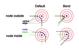
Also tweaking the precise location of the node compared to the vertices of the flexbody has a important role; Looking at the example where the node is outside a corner of a flexbody, is this flexbody will bend inward the corner will be relative sharp. If the node is put inside this corner the flexbody will bend in a more 'round' shape.
Nodes can made visual in-game by pressing 'CTRL N'. This will enable the node visualization mode and by pressing 'CTRL N' one will scroll trough all the various modes each having different information. Pressing it multiple times one will eventually turn it off. Pressing 'SHIFT CTRL N' one will scroll trough the available modes the opposite way. The UI will show in which visual mode one is.
There's also a second node visualization mode, enabled by pressing "CTRL M". This mode can show nodes as a simple point but can also show the speed or forces on the nodes, which can be useful when searching for "instabilities".
More info about the different nodes options: JBeam_Reference#nodes
Beams
More possible values and options can be found in the jbeam reference page
    "beams": [
          ["id1:", "id2:"],
          {"beamPrecompression":1, "beamType":"|NORMAL", "beamLongBound":1.0, "beamShortBound":1.0},
          //--RIGHT DOOR--
          {"beamSpring":2226840,"beamDamp":260},
          {"beamDeform":72750,"beamStrength":"FLT_MAX"},
          //door main shape
          ["d1r","d2r"],
          ["d2r","d3r"],
          ...
          {"deformGroup":"pickup_doorglass_R_break", "deformationTriggerRatio":0.01},
          //brittle glass beams
          {"beamDeform":21000,"beamStrength":14240},
          {"breakGroup":"pickup_doorglass_R"},
          ["d11r","d8r"],
          ...
          {"breakGroup":""},
          {"deformGroup":""},

          //rigidifier
          {"beamSpring":2226840,"beamDamp":325},
          {"beamDeform":2475,"beamStrength":"FLT_MAX"},
          ["d1r","d14r"],
           ...
          {"beamPrecompression":1, "beamType":"|NORMAL", "beamLongBound":1.0, "beamShortBound":1.0},
    ],
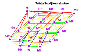
Between the nodes one has to put (weightless) beams. Regular beams can only cope with normal forces (push or pull), not with moment or torque, so if one wants to cope with that he should make a structure. It is tempting for some to just add beams in between all nodes. That certainly is possible but will create a structure what will react too uniform; for example beams in a door opening wouldn't be realistic as such an opening is relativly weak and would absorb the energy in a crash by bending rather than passing it on by being too stiff. In BeamNG most structures are separated in regular, crossing, rigid, rigifier and limiter beams. To explain what that means look at the drawn example.
At (A) there's only a simple beam (green). At (B), to simulate a flat plate, cross jbeams (yellow) are added to cope with the shear forces. At (C), rigid beams (blue) are added to make a stiffer structure, without it the nodes will rotate around each other. The rigid beams can cope with only a little moment, just like a flat plate can easily be bend. at (D), a rigifier node with beam (red) are added to stiffen up the structure. In real life, the shape of a part influences the stiffnes of the part like with small flanges. To still be able to cope with forces perpendicular to the structure and keep a simple jbeam structure rigifier beams are used. A limiter beam (orange) is often added to the edges of a structure to prevent stretching.
A example of the fullsize hood including the beams is shown in
Beams can also be used to have some degrees of freedom; consider nodes n1 fixed in space, a node n2 can move around n1 in a sphere if it's only attached with a single beam, if it's attached with two beams it will rotate around the axis and with three beams it will be non-movable. Using the version with two fixed nodes the lower A-arm of a suspension can be made e.g.
Every beam has it's own properties; the main properties that can be changes are the the spring, damp, break and bend values. The spring is how much a beam contracts or extend when a certain force is applied, damp is how quickly the energy is dissipated, break means when it breaks and bend when the beam changes length permanently.
It is often considered to have a as large as possible value for the spring property (otherwise it will look like pudding) but one has to take account that there is a maximum spring and damp value a node can handle. This is related to the nodeweight; a heavy node can cope with a larger spring/damp (or more beams) that a lightweight node. If this spring value is too large, the system becomes instable and can implode or 'eat itself'
If a beam may not break or bend permanently, one can assign a large value to this property, but it is considered cleaner to use "FLT_MAX" instead of a very large value.
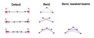
Tuning the values of beams in a structure can be a tedious job, but if often important to make things realistic. For example, most real-life structures like a H-beam (but also look at a hood and the area where the a-pillar is attached to the roof on crashed vehicles) will bend in a round-ish shape, but will buckle in a single location. Structures with a uniform second moment of area will for example buckle in the center. On the drawn example; on can lower the values of the rigid beam in the center but also add some extra rigid beams.
Besides 'Normal" beams there are lots of other beams, explained JBeam_Reference#beams. The most common other beams are Bounded and Support beams which react different of the amount they're stretched or contracted.
BeamCompression is also often used to change the length of a beam at spawn.
There are also two regularly used groups in the beams section: deformgroup and breakgroups;
The deformgroup has a triggerratio and when a beam in this group is contracted or stretched with this amount the deformgroup is triggered. This can change a material, like change the 'glass' material to a 'broken glass' material.
The Breakgroup is a group that if a single beam is broken all beams in this group will break. One can set the breakgroupType to 1, which means that a broken beam won't trigger the breakgroup but will break if the breakgroup is triggered.
It is VERY important to end all breakgroups and deformgroups in a beam section, otherwise beams in other jbeams can break or trigger the deform or breakgroup when a beam breaks.
Beams can made visual in-game by pressing 'CTRL B'. This will enable the beam visualization mode and by pressing 'CTRL B' one will scroll trough all the various modes each having different information. Pressing it multiple times one will eventually turn it off. Pressing 'SHIFT CTRL B' one will scroll trough the available modes the opposite way. The UI will show in which visual mode one is.
Hydros
    "hydros": [
            ["id1:","id2:"],
            {"beamPrecompression":1, "beamType":"|NORMAL", "beamLongBound":1.0, "beamShortBound":1.0},
            {"beamDeform":37500,"beamStrength":71200},
            {"beamSpring":256200,"beamDamp":2080},
            ["tsfbr4","tsfb11",{"inputSource":"parkingbrake","inLimit":0,"outLimit":1.85,"inRate":0.4,"outRate":0.5,"inputFactor":1.0}],
    ],
This section contains beams somewhat similar to regular beams, but in contrast to these regular beams hydro's can extend or retract themselves when a function is enabled. A more detailed explanation is given in the Hydros Wiki, but a simple hydro section contains beams defined like in the beam section, but with an inputsource line attached to it. In the example this hydro can only extend (inLimit is zero, outLimit is non-zero), the in- and outRate defines the speed of which the hydro contracts and/or expand. The inputFactor defines which way the hydro reacts - in case the hydro should only retract this value should be set to -1 besides changing the inLimit and outLimit.
Triangles & quads (Coltri's)
    "triangles": [
            ["id1:","id2:","id3:"],
            //tailgate
            {"group":"pickup_tailgateouter"},
            {"dragCoef":6},
            ["t2rr","t1rr","t2r"],
            ["t1rr","t1r","t2r"],
            ["t2r","t1r","t2"],
            ["t1r","t1","t2"],
            ...
            {"dragCoef":0},
            {"breakGroup":"pickup_tailgatelatch"},
            ["b5ll", "b10ll", "t2ll"],
            ...
            {"breakGroup":""},
            {"dragCoef":0},
    ],
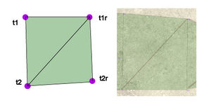
Triangles & quads are very similar too each other; they have the same purpose with the only difference that a triangle is set up using three nodes where a quad uses four. (the quad is introduced at a later state to make jbeaming easier) The quad is actually two triangles sharing two same nodes. They're almost always called a 'coltri' (collision triangle), which they will be referred as in this section. The Group option is not really necessary but can be useful in finding errors as the console can report in which group the error is located. Coltri's 'fill' the area between nodes, in a way that nodes from an other vehicle or even selfCollision enables nodes from its own vehicle can't pass this area. It isn't a parts of the force carrying structure like a beam - it only causes a force when a node tries to go trough it. This area has a front and a rear; the front won't allow nodes and coltri's from another vehicle or selfcollision enabled nodes from it's own vehicle to pass. This in contrast with the rear which will let those through. To define a front area; if you look at the nodes which should have a triangle or quad in between them, one should write down the nodes in counter-clockwise order. One can check if the coltri's are set up correctly by pressing 'CTRL T' in-game. A green area means the 'front' of a triangle or quad, a red area means the back of it. Pressing 'CTRL T' again makes them disappear again.
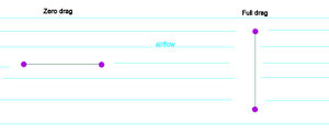
By adding a breakgroup to the coltri; one can disable the coltris inside this breakgroup when this breakgroup is triggered. This can be very useful so one can have coltris between separate parts (e.g. between doors and the body, or between the tailgate and the bed) so a parts won't be 'caught' that easily by other nodes, but will be disabled when a part falls of. Be careful to end all breakgroups. A 'dragCoef' can be added to simulate pressure drag across the area to simulate air drag and lift. E.g. wings and spoilers have commonly a large value, parts which normally aren't exposed to the outside have a large value. The last reason is that unfortunately currently if a coltri is situated behind another this second area does have the same drag as the front one. Also, the drag is calculated with the part of the coltri is perpendicular to the airflow. So a coltri which is parallel to the airflow won't cause any drag, in contract wit coltris/quads perpendicular to the airflow. But the both the front and rear of a coltri cause equal drag. Take care that, just like selfcollission enabled nodes, one should have a distance between selfcollission enabled nodes and coltri's of about 3 centimeter. Coltri's of a single vehicle can be placed next to each other or can even cross others.
Rails
The rails section is beyond this introduction; more info can be found in this Wiki page: Slidenodes. In short this section works closely together with the slidenodes section. The rails section defines the rails between two or more nodes on which the slidenodes can move. Be aware that this section starts and ends with a '{' and '}' respectively!
Slidenodes
The slidenodes section, like rails section is beyond this introduction; more info can be found at the same Wike page as the rails section: Slidenodes. This section defines which nodes can slide over which rails.
Testing
Once the jbeams are set up, the final thing is testing and improving the jbeams. When there's an error, the game freezes when loading the vehicle. Errors often occur; it happens to most (maybe all?) of us and most of the times it will be a simple forgotten comma or bracket. Remember to open the console (often with the '~' key but it can be different) and look for error. If the entire screen is filled with red lines, scroll to the beginning of those lines. What's wrong should be explained there. You can try to fix it, but if it seems you can't find the issue you can add '//' before a line disabling it, or even disabling a part of the Flexbody by putting '/*' at the start and '*/' at the end. By disabling one can close in in errors. But remember that:
- There can't be a /*....*/ section in between another /*...*/ section.
- Even with disabling sections, every opening bracket still needs a closing bracket.
If a part behaves strangely, visualize the jbeam to see what's happening. To have some beams stand out of the rest, one can 'highlight' a beam by adding a line to the beam:
["node1","node2"{"highlight":{"radius":0.005, "col":"#ff0000ff" }}],
This beam will then show up under every beam visualization mode. The first six digits mean the HEX colour (so in this case pure red) and the last two is the alpha channel, so how well it is visible (00 being invisible, ff being full visible)
There's a page dedicated to common errors and problem solving: Vehicle Modding Common Problems
If you're somewhat serious about modding, have read the wiki pages (and checked out the forum if the answer may be already answered there) and still have questions or keep running into problems, there are 'mod support meetings' planned. If it really can't wait, don't hesitate to contact the Staff.
| Vehicle Creation | ||||||||||||||||
|---|---|---|---|---|---|---|---|---|---|---|---|---|---|---|---|---|
| Get started: Introduction to Vehicle Creation | ||||||||||||||||
| ||||||||||||||||
| See also: JBeam Examples • JBeam Physics Theory |

